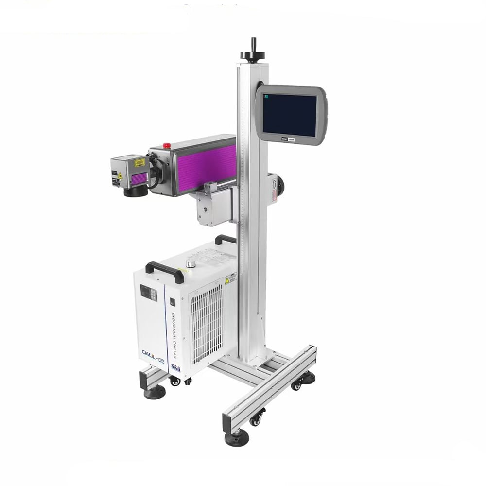
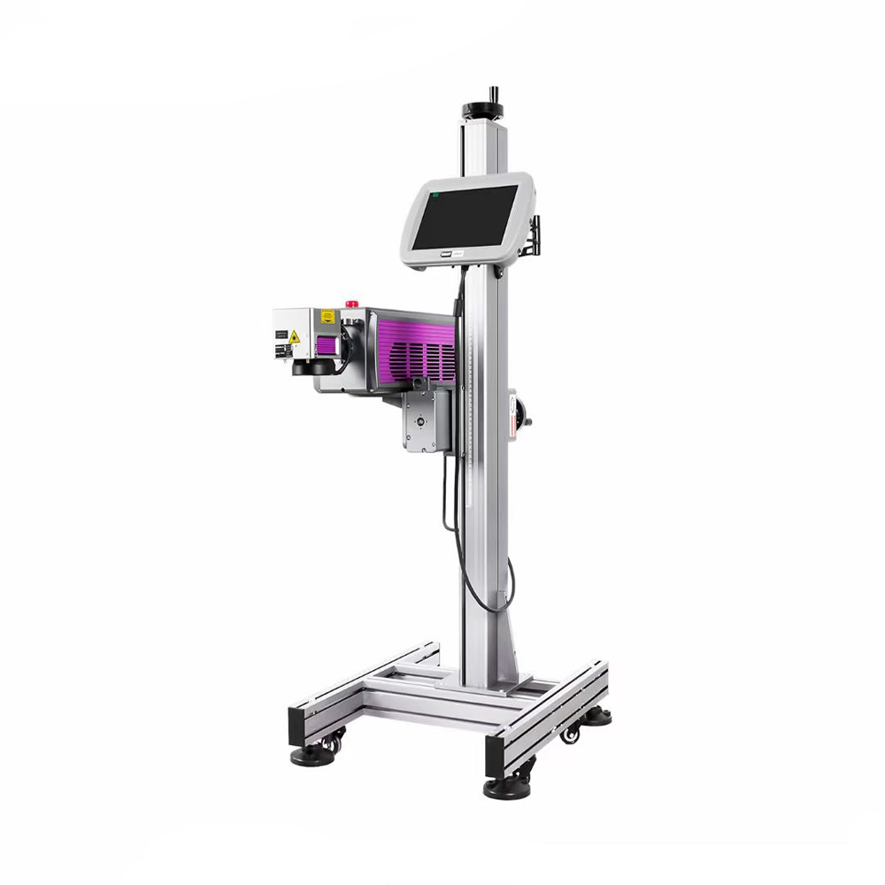
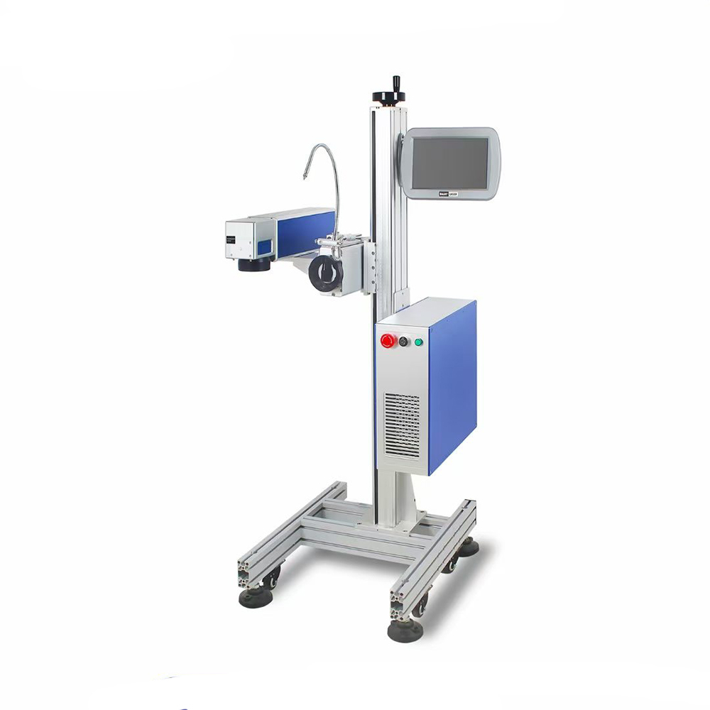
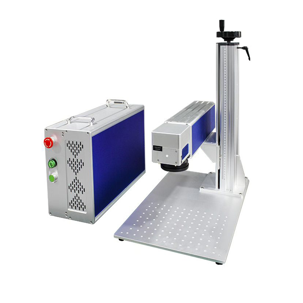
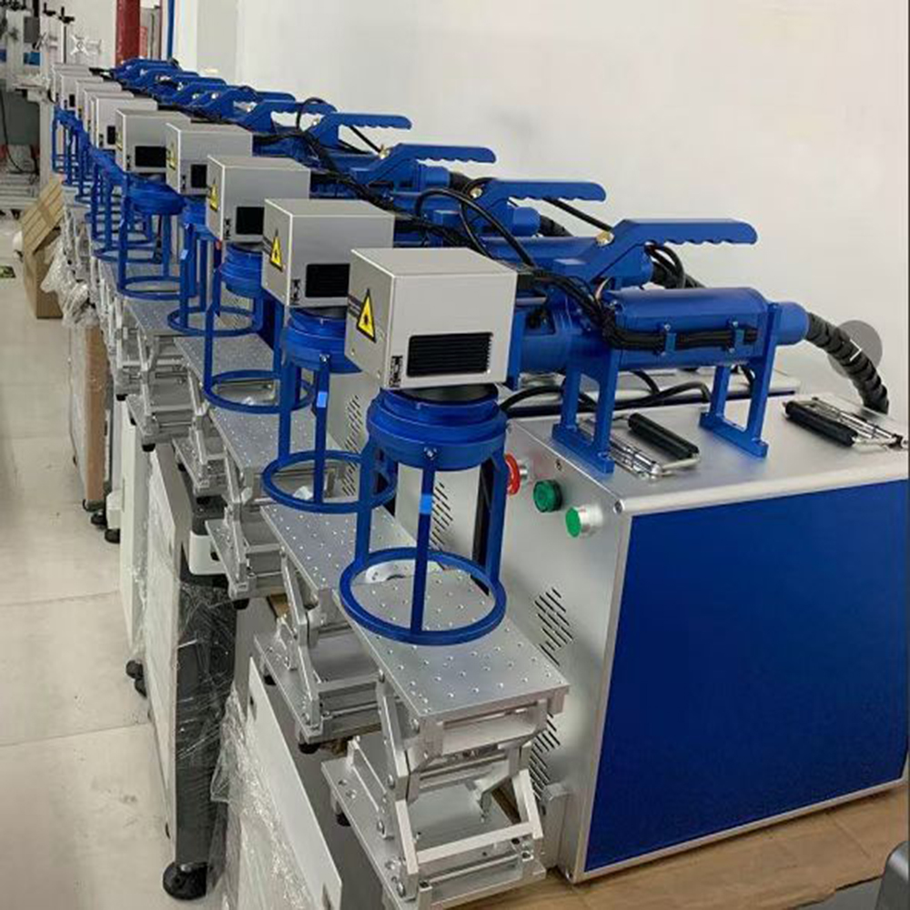
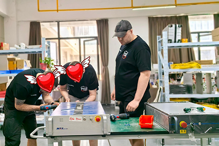
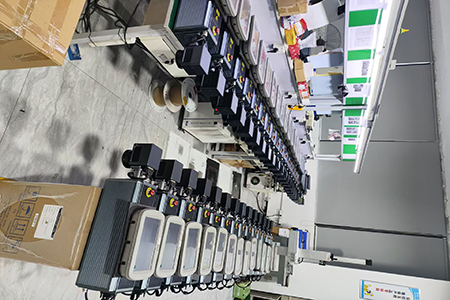
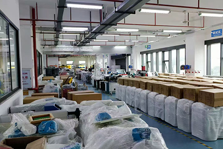
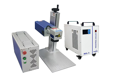
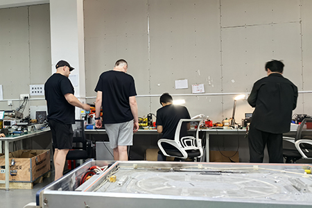
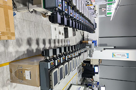
This course focuses on practical operations including galvanometer selection, field‑lens selection, control‑card and software installation, and laser source commissioning. It covers general assembly & commissioning, process parameters, fault diagnosis and on‑the‑fly pipeline marking for the full series of fiber, UV and CO₂ laser marking equipment.
I. Equipment Assembly and Commissioning
Practical operations: galvanometer selection, field‑lens selection, control‑card & software installation, laser‑source commissioning, optical‑path alignment
- Galvanometer Selection & Matching Select galvanometers according to laser wavelength and output spot size. For fiber lasers of 20‑50 W, adopt digital galvanometers with 10 mm spot; for 50‑100 W fiber lasers, use 14 mm‑spot digital galvanometers. For UV equipment, prioritize high‑precision digital galvanometers with 10 mm spot. For CO₂ equipment, adopt dedicated 10.6 μm infrared galvanometers. Digital galvanometers are preferred, with repeat positioning accuracy ≤ 12 μrad and stronger anti‑interference performance compared with analog types. High‑response galvanometers shall be equipped for high‑speed RF marking scenarios. Fasten the 25‑pin signal connector during installation and ensure reliable earthing to avoid signal interference.
-
Field‑lens Selection & Matching Field lenses must strictly match the wavelength and galvanometer input spot of the equipment. Inter‑model mixing is prohibited. Ordinary quartz field lenses are used for fiber lasers; special UV quartz field lenses for UV equipment; ZnSe zinc‑selenide field lenses for CO₂ equipment. Do not touch the coated surface with bare hands. Select focal length according to marking field‑of‑view: short focal length for fine small‑size workpieces; F160 for general‑purpose applications; F254 for large‑area marking. Mismatching will cause edge distortion of marking patterns. For contaminated lenses, use lens tissue soaked in 3:1 mixed solution of anhydrous alcohol‑ether and wipe spirally from center to edge.
- Control‑card and Control‑software Installation Select the corresponding marking control card based on laser type. For fiber lasers, connect the laser source and control card via 68‑pin SCSI cable. After installing marking software on the industrial PC, disable real‑time anti‑virus protection to prevent occupation of real‑time computing resources. Switch the communication protocol among fiber / UV / CO₂ modes inside software according to equipment type. Connect modulation signal cables for RF‑tube lasers and adapt high‑voltage drive interfaces for glass‑tube lasers. Multi‑card parallel operation is supported; encoders can be externally connected for on‑the‑fly marking.
-
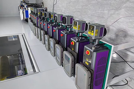
Laser Source Commissioning For fiber MOPA pulse lasers: reserve ≥ 10 cm clearance around the laser for heat dissipation. The minimum bending radius of fiber shall be ≥ 200 mm; sharp bending is forbidden. Pre‑heat for 60 s after power‑on, set power to zero, run empty frame scanning, then gradually raise output power. For water‑cooled UV lasers: check water‑chiller liquid level before startup. Set water temperature at 22‑25 °C. Do NOT enable laser output until temperature reaches the set value. For CO₂ lasers: ensure normal water circulation for water‑cooled glass tubes; verify air‑/water‑cooling conditions and modulation wiring for RF metal tubes. Use ceramic conversion sheet to inspect output laser spot. Qualified spot is circular and uniformly distributed without dark spots or notches.
 |
 |
II. Core Laser Marking Process Parameters
Key adjustable parameters: laser power, frequency, pulse width, scanning speed, hatch spacing, defocus amount
Power determines marking depth. Low frequency fits deep engraving; high frequency fits fine color marking. Narrow pulse width reduces thermal influence. Positive / negative defocus mitigates heat accumulation during processing.
| Processing Target |
Reference Parameters |
| White marking on stainless steel |
Hatch spacing 0.1 mm, scanning speed 1200‑1500 mm/s, power 20 % |
| Black marking on stainless steel |
Hatch spacing 0.03‑0.05 mm, scanning speed 100‑200 mm/s, power 80 % |
| Metal deep engraving |
Negative defocus 2‑4 mm, arched cross hatching |
| Color marking on stainless steel |
Narrow pulse width, hatch spacing 0.001‑0.002 mm |
| Marking on painted plastic |
Hatch spacing 0.1 mm, scanning speed 1000‑2000 mm/s, power 25‑30 % |
III. Common Fault Diagnosis
- Blurred / faint marking patterns: Field‑lens protective cover not removed; contamination on field lens / protective window; focal‑point offset; galvanometer zero‑point drift; mismatched spot specifications between galvanometer and field lens.
- Over‑melting / burnt workpiece: Excessively high laser power; scanning speed too low; too small hatch spacing leading to severe thermal accumulation.
- Rough engraved surface: Excessive single‑pulse energy; improper settings of hatch angle & pulse overlap ratio; cross‑hatching function not enabled.
- Incomplete vector graphics with broken segments: Native breakpoint defects in original CAD vector file; abnormal vector parsing by software. Repair graphics in drawing software in advance.
- Normal red‑dot indicator but no laser output: Loose laser communication wiring; wrong laser‑protocol selection in software; emergency‑stop button not reset; laser triggered over‑heat or safety protection.
-
Stretched / misplaced patterns in on‑the‑fly marking: Reversed encoder wiring direction; incorrect pulse‑equivalent parameter; mismatch between photo‑electric trigger delay and production‑line speed.
 |
 |
IV. Pipeline On‑the‑Fly Marking
Applied for online marking of batch numbers, serial numbers and production dates on production lines.
- Hardware Composition: Laser marking host, conveyor belt, rotary encoder, photoelectric trigger sensor. The encoder collects real‑time line speed and feeds data back to control card for real‑time scanning‑trajectory correction.
- Commissioning Key Points: Correctly configure encoder pulse equivalent and rotation direction in software. Set proper photoelectric trigger delay. Variable text can be imported from Excel files for automatic serial‑number increment. Actual line speed shall not exceed the maximum scanning speed of galvanometer.
- Mass‑production Maintenance: Complete first‑article inspection for each batch. Periodically inspect encoder pressure roller and eliminate belt deviation. Increase field‑lens maintenance frequency under heavy‑dust working conditions.

 EN
EN
 AR
AR CS
CS NL
NL FR
FR DE
DE IT
IT JA
JA KO
KO PL
PL PT
PT RU
RU ES
ES UK
UK TH
TH TR
TR