All Categories

Selective Laser Melting (SLM)

Home >  Products >  Laser Additive Manufacturing >  Selective Laser Melting (SLM)

PRODUCTS

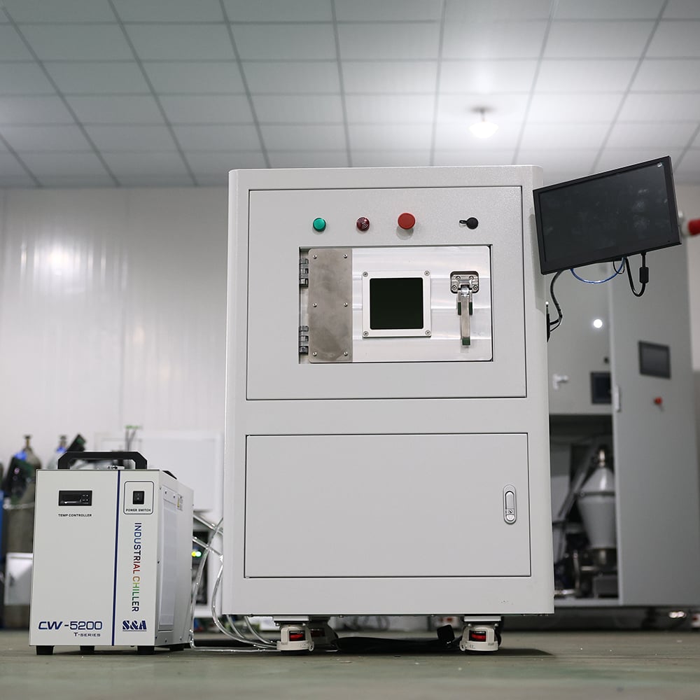
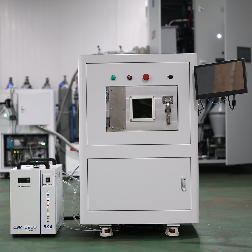
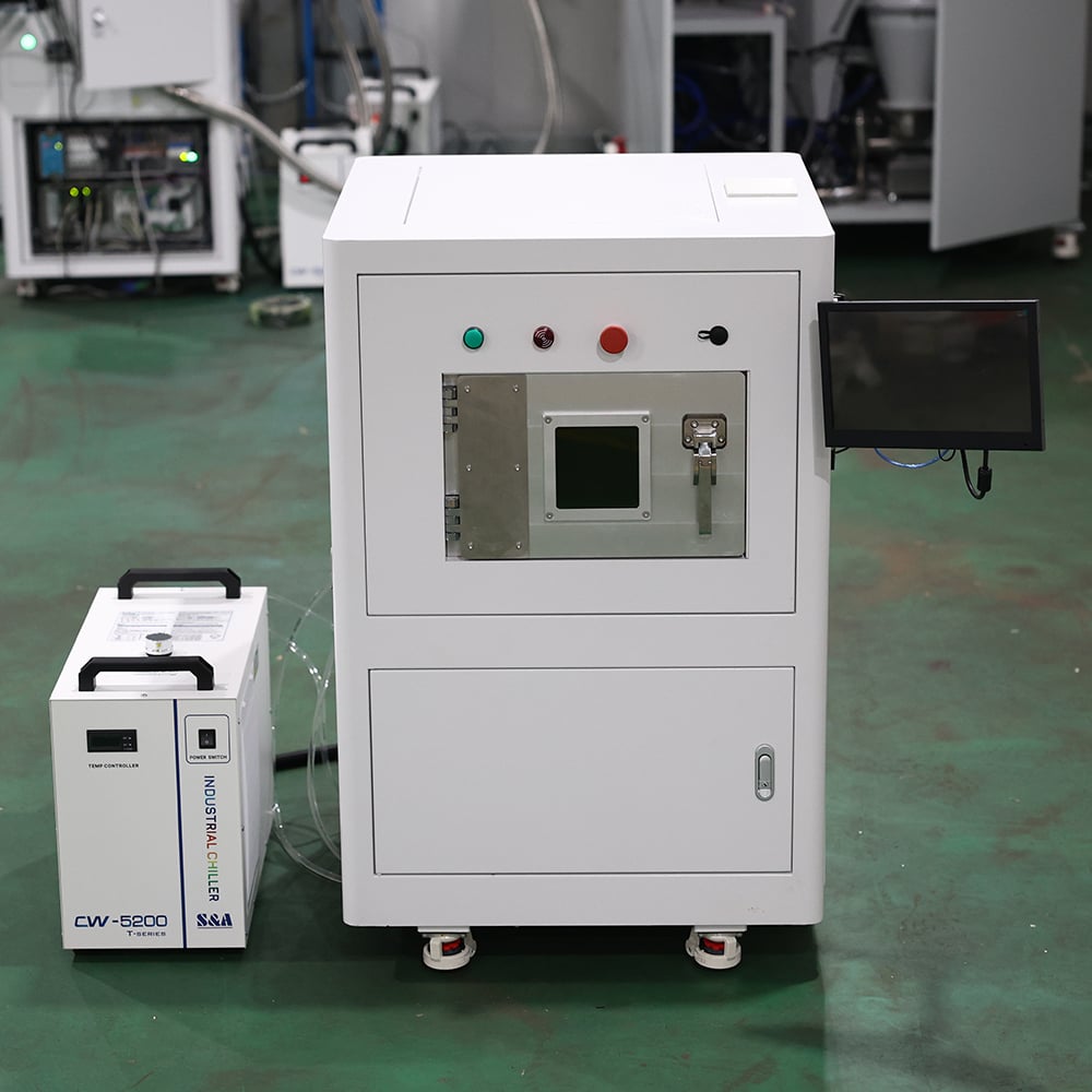
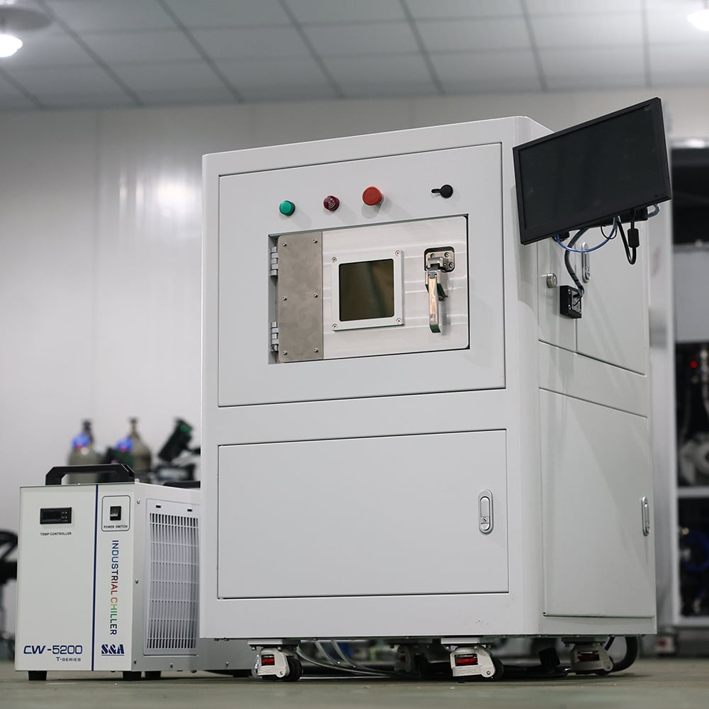
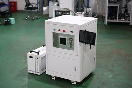
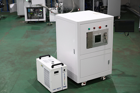
M120 SLM Metal 3D Printer

M120 SLM Metal 3D Printer

Overview of SLM Technology

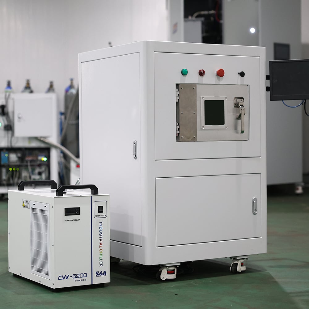
Selective Laser Melting Process.JPG Selective Laser Melting Process3.JPG

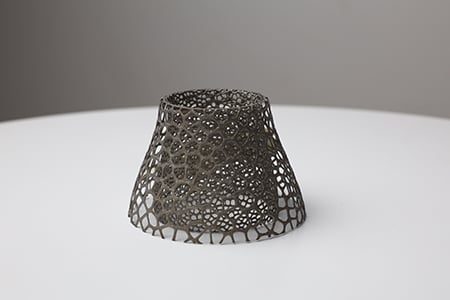
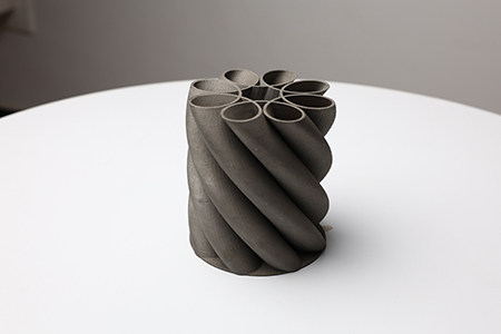
SLM stands for Selective Laser Melting, a powder‑bed metal additive‑manufacturing process. A high‑energy fiber laser beam melts metal powder completely layer‑by‑layer according to scanning paths generated by slicing software to produce high‑density functional metal parts. The forming process is performed inside a sealed inert‑gas‑protected chamber to prevent metal‑powder oxidation. It enables the fabrication of complex geometries such as lattices, conformal cooling channels and intricate internal cavities which are difficult to achieve via conventional machining. It is widely applied in research institutes, dental medical applications, mold development and small‑batch precision‑part trial production.

M120 Metal 3D Printer Configuration Table

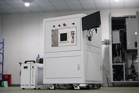
Selective Laser Melting Process1.JPG Selective Laser Melting Process2.JPG
Sub‑system Key Components Configuration Description
Optical System Fiber Laser 300 W fiber laser, wavelength 1060‑1080 nm with closed‑loop power feedback
Scanning Galvanometer Closed‑loop grating control with red‑laser beam indicator
F‑θ Lens & Beam Expander Quartz optical lenses
Gas Circuit System Oxygen‑content Analyzer Real‑time forming‑chamber oxygen monitoring with auto‑alarm for abnormal values
Chamber‑purging Gas Circuit, Circulating‑shield‑gas Circuit, Gas‑purification Unit Self‑developed gas system with argon circulation protection and right‑side air‑wall design
Forming System Top‑feeding Powder Storage System Safe and reliable with large powder capacity
Unidirectional Flexible Silicone‑rubber Coater System Single‑blade bidirectional recoating with overload‑protection alarm
Sealed Forming Chamber Stainless‑steel / high‑strength‑aluminum‑alloy chamber, safety door lock and built‑in LED lighting
Build Cylinder Assembly Leading‑brand lead‑screw and guide rails; substrate pre‑heating up to 180 °C
Control & Software System Data‑slicing Software Supports STL / SLC formats, multi‑mode filling strategies and open process parameters
Machine‑control Software Chinese UI; real‑time monitoring of oxygen level, coater position and job progress; automatic fault‑diagnosis and alarm

M120 Metal 3D Printer Performance Specifications

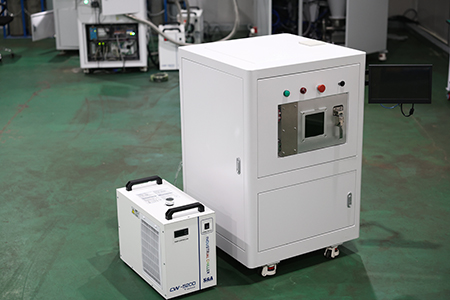
Selective Laser Melting Process3.JPG Selective Laser Melting Process4.JPG
Item Specification
Model M120
Process Selective Laser Melting (SLM)
Maximum Build Size Φ120 mm × 100 mm (including substrate)
Dimensional Accuracy ≤100 mm: ±0.1 mm;>100 mm: ±0.1%×L
Layer Thickness Adjustable 20‑100 μm
Laser Source 300 W fiber laser, wavelength 1060‑1080 nm; output 10%‑100% adjustable
Scanning Speed 0‑7 m/s
Minimum Spot Diameter 60 μm±10 μm
Oxygen‑level Control ≤1000 ppm
Substrate Pre‑heating Temperature Max. 180 °C
Compatible Materials Stainless steel, high‑temperature alloys, dental‑grade metals (Mg & Al‑based alloys excluded)
Total Power Consumption Approx. 8 kW
Power Supply AC380V±5%, three‑phase five‑wire system
Ambient Temperature (23±5) °C
Relative Humidity ≤75% RH
Overall Machine Dimensions 500×500×980 mm
Machine Weight Approx. 350 kg
Import Data Format STL, SLC

Operation & Maintenance Instructions

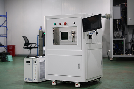
SLM Metal Printing.JPG SLM Metal Printing0.JPG

Operating Specifications

  1. Environment & Power Supply: Equip the workshop with air‑conditioning to maintain required temperature and humidity. Install Class‑D fire extinguishers and reliable earthing (ground resistance ≤5 Ω). Avoid sharing power supply with high‑frequency interference equipment.
  2. Shielding Gas: Prepare ≥40 L high‑purity argon (purity ≥99.9%) for chamber purging and gas circulation.
  3. Powder‑handling Safety: Wear respirators, protective suits and gloves when handling metal powder. Use explosion‑proof vacuum cleaners for reactive powders such as titanium alloy. Dispose of waste powder as hazardous chemical waste per regulations.
  4. Laser Safety: This is a Class‑4 laser device. Never open the forming‑chamber door during operation. Do not remove safety interlocks.
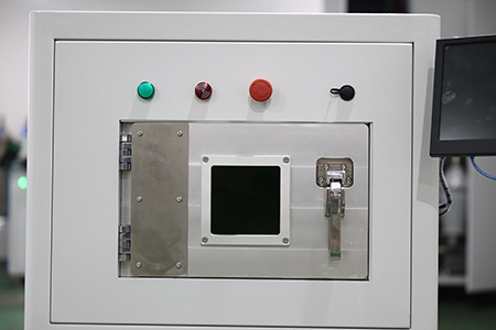
  5. Printing Workflow: Inspect substrate flatness and coater condition before printing. Start laser only after oxygen content falls within allowable range. Press emergency‑stop button to halt the whole machine in case of anomalies.

Routine Maintenance

  1. Optical System: Never touch F‑θ lens, beam expander or other optical elements with bare hands. For lens contamination, contact qualified technicians for cleaning and calibration. Non‑professionals must not disassemble laser source or galvanometer.
  2. Mechanical Forming Unit: Clean forming chamber and cylinder, remove powder residues on coater after each build. Replace silicone‑rubber coater blades when worn. Clean and lubricate Z‑axis lead‑screws and guide rails periodically.
  3. Gas Circuit System: Calibrate oxygen sensor regularly; inspect argon pipelines for leakage; maintain gas‑purification units and replace filter consumables as scheduled.
  4. Software & Backup: Back‑up process parameters periodically. All software‑version upgrades shall be performed by the manufacturer. Keep operation logs and alarm records for troubleshooting.
  5. Spare Parts: Stock consumables such as substrates, silicone‑rubber coater blades and seals. The machine and laser carry a 1‑year warranty. Contact manufacturer engineers for malfunctions; dis‑assembly by end‑users is not recommended.

inquiry
Contact Us

Our friendly team would love to hear from you!

Your Name *
Phone *
E-mail *
Your Inquiry